


历史上的今天
今天是:2025年03月29日(星期六)
2019年03月29日 | STM8L15x for IAR点亮LED
2019-03-29 来源:eefocus
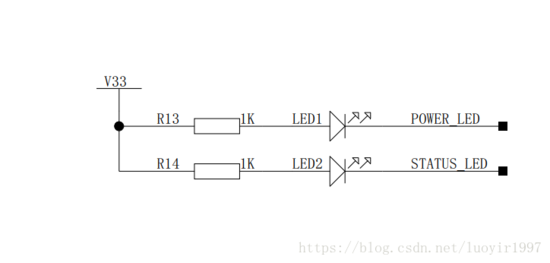
一、电路分析
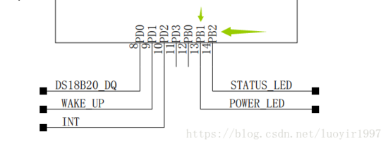
STM8L151G6U6 的LED有两个,分别是 :LED1:POWER_LED ---- PB1 ;
LED2:STATUS_LED ---- PB2
二、IAR新建工程准备
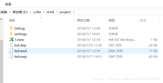
1.在项目文件夹里创建3个文件夹
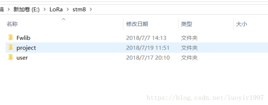
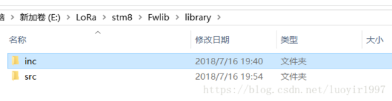
2.fWLIB用来存放stm8板子的各种配置头文件和.c文件
3.project用来存放工程文件和debug日志
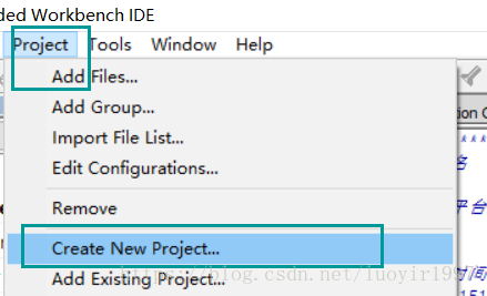
三、新建工程
1.Create New Project
.
2.选择工程模板------c,将工程命名为led,将工程文件保存在project下
3.addd flies

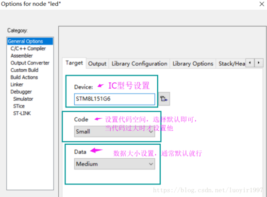
四、配置选项卡
1.右键选项

2.GO --->target
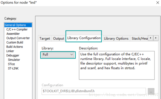
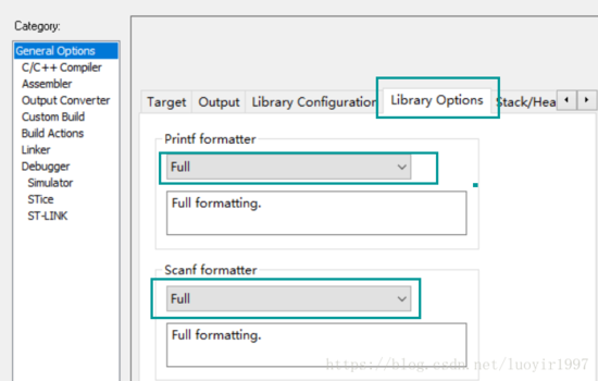
3.GO----->library C
4..GO----->library O
5.C/C++---->Optimitions 代码的优化

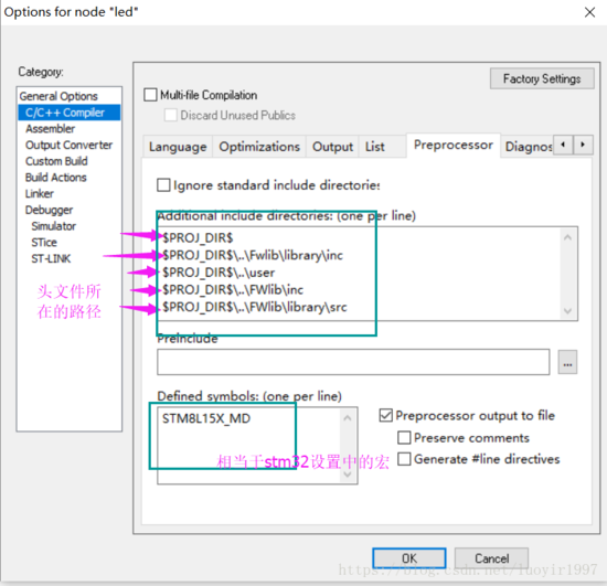
6.C/C++---->preprocessor
$PROJ_DIR$ 表示用户建项目的当前目录,途中显示的有stm8115x_conf头文件在项目中会使用,如果不把用户文件夹包含进来会报错 显示找不到stm8115x_conf.h头文件。
$PROJ_DIR$..Fwliblibraryinc
$PROJ_DIR$..user
$PROJ_DIR$..FWlibinc
$PROJ_DIR$..FWliblibrarysrc
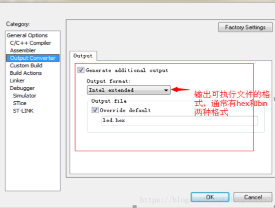
7.Output converter 设置输出的可执行文件的形式,通常有hex和bin两种形式:
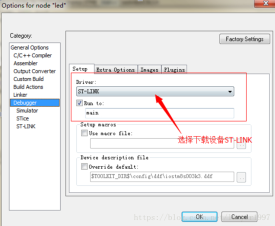
8.设置下载工具的类型,STM8可以支持串口下载(比较麻烦!)和ST-LINK下载,我们用ST-LINK下载
五、代码的编写
1.main.c
#include "stm8_board.h"
#include "timing_delay.h"
int main( void )
{
turn_led(LED_STATUS, OFF);
}
2.led.c
/****************************************
*文件名 :led.c
*描述 :GPIO口配置函数库
*实验平台:STM8L151g6开发板
*作者 :LUOYIRAN
*QQ :969303624
*修改时间:2018.7.15
*STM8L151g6开发板硬件连接
|--------------------|
| LED1-power-PB1 |
| LED2-status-PB2 |
|--------------------|
*****************************************/
#include "led.h"
#include "stm8l15x_gpio.h"
void turn_led(uint8_t which, uint8_t cmd)
{
if(OFF == cmd) //如果发出关闭信号
{
if(which == LED_POWER) //如果要关LED1
GPIO_Init(SYSRUN_LED_PIN, GPIO_Mode_Out_PP_High_Slow);//初始化LED1
else if(which == LED_STATUS) //如果要关LED2
GPIO_Init(LED_STATUS_PIN, GPIO_Mode_Out_PP_High_Slow);//初始化LED2
}
else //如果发起开启信号
{
if(which == LED_POWER) //如果要开LED1
GPIO_Init(SYSRUN_LED_PIN, GPIO_Mode_Out_PP_Low_Slow); //初始化LED1
else if(which == LED_STATUS)//如果要开LED2
GPIO_Init(LED_STATUS_PIN, GPIO_Mode_Out_PP_Low_Slow); //初始化LED2
}
}
LED.H
#ifndef __LED_H
#define __LED_H
#include "stm8_board.h"
#include "timing_delay.h"
#include "stm8l15x.h"
#include "stm8l15x_gpio.h"
extern void turn_led(uint8_t which, uint8_t cmd);
#endif /*__LED_H*/
3.gpio.c/gpio.h(从库里拿)
#include "stm8l15x_gpio.h"
/** @addtogroup STM8L15x_StdPeriph_Driver
* @{
*/
/** @addtogroup I2C
* @{
*/
/* Exported types ------------------------------------------------------------*/
/** @addtogroup GPIO_Exported_Types
* @{
*/
/**
* @defgroup GPIO_Modes
*
* @brief
*
* Bits definitions:
* - Bit 7: 0 = INPUT mode
* 1 = OUTPUT mode
* 1 = PULL-UP (input) or PUSH-PULL (output)
* - Bit 5: 0 = No external interrupt (input) or No slope control (output)
* 1 = External interrupt (input) or Slow control enabled (output)
* - Bit 4: 0 = Low level (output)
* 1 = High level (output push-pull) or HI-Z (output open-drain)
* @{
*/
/**
* @}
*/
/** @defgroup GPIO_Pin
* @{
*/
/**
* @}
*/
/**
* @}
*/
/* Exported constants --------------------------------------------------------*/
/* Exported macros -----------------------------------------------------------*/
/** @addtogroup GPIO_Exported_Macros
* @{
*/
/**
* @brief Macro used by the assert function to check the different functions parameters.
*/
/**
* @brief Macro used by the assert function in order to check the different
* values of GPIOMode_TypeDef.
*/
#define IS_GPIO_MODE(MODE)
(((MODE) == GPIO_Mode_In_FL_No_IT) ||
((MODE) == GPIO_Mode_In_PU_No_IT) ||
((MODE) == GPIO_Mode_In_FL_IT) ||
((MODE) == GPIO_Mode_In_PU_IT) ||
((MODE) == GPIO_Mode_Out_OD_Low_Fast) ||
((MODE) == GPIO_Mode_Out_PP_Low_Fast) ||
((MODE) == GPIO_Mode_Out_OD_Low_Slow) ||
((MODE) == GPIO_Mode_Out_PP_Low_Slow) ||
((MODE) == GPIO_Mode_Out_OD_HiZ_Fast) ||
((MODE) == GPIO_Mode_Out_PP_High_Fast) ||
((MODE) == GPIO_Mode_Out_OD_HiZ_Slow) ||
((MODE) == GPIO_Mode_Out_PP_High_Slow))
/**
* @brief Macro used by the assert function in order to check the different
* values of GPIO_Pins.
*/
#define IS_GPIO_PIN(PIN) ((PIN) != (uint8_t)0x00)
/**
* @}
*/
/* Exported functions ------------------------------------------------------- */
/* Initialization and Configuration *******************************************/
void GPIO_DeInit(GPIO_TypeDef* GPIOx);
void GPIO_Init(GPIO_TypeDef* GPIOx, uint8_t GPIO_Pin, GPIO_Mode_TypeDef GPIO_Mode);
void GPIO_ExternalPullUpConfig(GPIO_TypeDef* GPIOx, uint8_t GPIO_Pin, FunctionalState NewState);
/* GPIO Read and Write ********************************************************/
void GPIO_Write(GPIO_TypeDef* GPIOx, uint8_t GPIO_PortVal);
void GPIO_WriteBit(GPIO_TypeDef* GPIOx, GPIO_Pin_TypeDef GPIO_Pin, BitAction GPIO_BitVal);
void GPIO_SetBits(GPIO_TypeDef* GPIOx, uint8_t GPIO_Pin);
void GPIO_ResetBits(GPIO_TypeDef* GPIOx, uint8_t GPIO_Pin);
void GPIO_ToggleBits(GPIO_TypeDef* GPIOx, uint8_t GPIO_Pin);
uint8_t GPIO_ReadInputData(GPIO_TypeDef* GPIOx);
uint8_t GPIO_ReadOutputData(GPIO_TypeDef* GPIOx);
BitStatus GPIO_ReadInputDataBit(GPIO_TypeDef* GPIOx, GPIO_Pin_TypeDef GPIO_Pin);
BitStatus GPIO_ReadOutputDataBit(GPIO_TypeDef* GPIOx, GPIO_Pin_TypeDef GPIO_Pin);
/**
* @}
*/
/**
* @}
*/
/************************ (C) COPYRIGHT STMicroelectronics *****END OF FILE****/
#include "stm8l15x_gpio.h"
/** @addtogroup STM8L15x_StdPeriph_Driver
* @{
*/
/** @defgroup CLK
* @brief CLK driver modules
* @{
*/
/* Private typedef -----------------------------------------------------------*/
/* Private define ------------------------------------------------------------*/
/* Private macro -------------------------------------------------------------*/
/* Private variables ---------------------------------------------------------*/
/* Private function prototypes -----------------------------------------------*/
/* Private functions ---------------------------------------------------------*/
/** @defgroup GPIO_Private_Functions
* @{
*/
/** @defgroup GPIO_Group1 Initialization and Configuration
* @brief Initialization and Configuration
*
@verbatim
===============================================================================
Initialization and Configuration
===============================================================================
@endverbatim
* @{
*/
/**
* @brief Deinitializes the GPIOx peripheral registers to their default reset values.
* @param GPIOx: Select the GPIO peripheral number (x = A to I).
* @retval None
*/
void GPIO_DeInit(GPIO_TypeDef* GPIOx)
{
GPIOx->CR2 = GPIO_CR2_RESET_VALUE; /* Reset Control Register 2 */
GPIOx->ODR = GPIO_ODR_RESET_VALUE; /* Reset Output Data Register */
GPIOx->DDR = GPIO_DDR_RESET_VALUE; /* Reset Data Direction Register */
GPIOx->CR1 = GPIO_CR1_RESET_VALUE; /* Reset Control Register 1 */
}
/**
* @brief Initializes the GPIOx according to the specified parameters.
* @param GPIOx : Select the GPIO peripheral number (x = A to I).
* @param GPIO_Pin : This parameter contains the pin number
* This parameter can be one of the following values:
* @arg GPIO_Pin_0: Pin 0
* @arg GPIO_Pin_1: Pin 1
* @arg GPIO_Pin_2: Pin 2
* @arg GPIO_Pin_3: Pin 3
* @arg GPIO_Pin_4: Pin 4
* @arg GPIO_Pin_5: Pin 5
* @arg GPIO_Pin_6: Pin 6
* @arg GPIO_Pin_7: Pin 7
* @param GPIO_Mode : This parameter can be a value of the
* This parameter can be one of the following values:
* @arg GPIO_Mode_In_FL_No_IT: Input floating, no external interrupt
* @arg GPIO_Mode_In_PU_No_IT: Input pull-up, no external interrupt
* @arg GPIO_Mode_In_FL_IT: Input pull-up, external interrupt
* @arg GPIO_Mode_Out_OD_Low_Fast: Output open-drain, low level, 10MHz
* @arg GPIO_Mode_Out_PP_Low_Fast: Output push-pull, low level, 10MHz
* @arg GPIO_Mode_Out_OD_Low_Slow: Output open-drain, low level, 2MHz
* @arg GPIO_Mode_Out_PP_Low_Slow: Output push-pull, low level, 2MHz
* @arg GPIO_Mode_Out_OD_HiZ_Fast: Output open-drain, high-impedance level, 10MHz
* @arg GPIO_Mode_Out_PP_High_Fast: Output push-pull, high level, 10MHz
* @arg GPIO_Mode_Out_OD_HiZ_Slow: Output open-drain, high-impedance level, 2MHz
* @arg GPIO_Mode_Out_PP_High_Slow: Output push-pull, high level, 2MHz
* @retval None
*/
void GPIO_Init(GPIO_TypeDef* GPIOx, uint8_t GPIO_Pin, GPIO_Mode_TypeDef GPIO_Mode)
{
/*----------------------*/
/* Check the parameters */
/*----------------------*/
assert_param(IS_GPIO_MODE(GPIO_Mode));
assert_param(IS_GPIO_PIN(GPIO_Pin));
/* Reset corresponding bit to GPIO_Pin in CR2 register */
GPIOx->CR2 &= (uint8_t)(~(GPIO_Pin));
/*-----------------------------*/
/* Input/Output mode selection */
/*-----------------------------*/
if ((((uint8_t)(GPIO_Mode)) & (uint8_t)0x80) != (uint8_t)0x00) /* Output mode */
{
if ((((uint8_t)(GPIO_Mode)) & (uint8_t)0x10) != (uint8_t)0x00) /* High level */
{
GPIOx->ODR |= GPIO_Pin;
} else /* Low level */
{
GPIOx->ODR &= (uint8_t)(~(GPIO_Pin));
}
/* Set Output mode */
GPIOx->DDR |= GPIO_Pin;
} else /* Input mode */
{
/* Set Input mode */
GPIOx->DDR &= (uint8_t)(~(GPIO_Pin));
}
/*------------------------------------------------------------------------*/
/* Pull-Up/Float (Input) or Push-Pull/Open-Drain (Output) modes selection */
/*------------------------------------------------------------------------*/
if ((((uint8_t)(GPIO_Mode)) & (uint8_t)0x40) != (uint8_t)0x00) /* Pull-Up or Push-Pull */
{
GPIOx->CR1 |= GPIO_Pin;
} else /* Float or Open-Drain */
{
GPIOx->CR1 &= (uint8_t)(~(GPIO_Pin));
}
/*-----------------------------------------------------*/
/* Interrupt (Input) or Slope (Output) modes selection */
/*-----------------------------------------------------*/
if ((((uint8_t)(GPIO_Mode)) & (uint8_t)0x20) != (uint8_t)0x00) /* Interrupt or Slow slope */
{
GPIOx->CR2 |= GPIO_Pin;
} else /* No external interrupt or No slope control */
{
GPIOx->CR2 &= (uint8_t)(~(GPIO_Pin));
}
}
/**
* @brief Configures the external pull-up on GPIOx pins.
* @param GPIOx : Select the GPIO peripheral number (x = A to I).
* @param GPIO_Pin : Specifies the pin number
* This parameter can be one of the following values:
* @arg GPIO_Pin_0: Pin 0
* @arg GPIO_Pin_1: Pin 1
* @arg GPIO_Pin_2: Pin 2
* @arg GPIO_Pin_3: Pin 3
* @arg GPIO_Pin_4: Pin 4
* @arg GPIO_Pin_5: Pin 5
* @arg GPIO_Pin_6: Pin 6
* @arg GPIO_Pin_7: Pin 7
* @param NewState : The new state of the pull up pin.
* Can be ENABLE or DISABLE
* @retval None
*/
void GPIO_ExternalPullUpConfig(GPIO_TypeDef* GPIOx, uint8_t GPIO_Pin, FunctionalState NewState)
{
/* Check the parameters */
assert_param(IS_GPIO_PIN(GPIO_Pin));
assert_param(IS_FUNCTIONAL_STATE(NewState));
if (NewState != DISABLE) /* External Pull-Up Set*/
{
GPIOx->CR1 |= GPIO_Pin;
} else /* External Pull-Up Reset*/
{
GPIOx->CR1 &= (uint8_t)(~(GPIO_Pin));
}
}
/**
* @}
*/
/** @defgroup GPIO_Group2 GPIO Read and Write
* @brief GPIO Read and Write
*
@verbatim
===============================================================================
GPIO Read and Write
===============================================================================
@endverbatim
* @{
*/
/**
* @brief Writes data to the specified GPIO data port.
* @note The port must be configured in output mode.
* @param GPIOx : Select the GPIO peripheral number (x = A to I).
* @param GPIO_PortVal : Specifies the value to be written to the port output
* data register.
* @retval None
*/
void GPIO_Write(GPIO_TypeDef* GPIOx, uint8_t GPIO_PortVal)
{
GPIOx->ODR = GPIO_PortVal;
}
/**
* @brief Sets or clears the selected data port bit.
* @param GPIOx : Select the GPIO peripheral number (x = A to I).
* @param GPIO_Pin: Specifies the port bit to be written.
* This parameter can be one of the following values:
* @arg GPIO_Pin_0: Pin 0
* @arg GPIO_Pin_1: Pin 1
* @arg GPIO_Pin_2: Pin 2
* @arg GPIO_Pin_3: Pin 3
* @arg GPIO_Pin_4: Pin 4
* @arg GPIO_Pin_5: Pin 5
* @arg GPIO_Pin_6: Pin 6
* @arg GPIO_Pin_7: Pin 7
* @param GPIO_BitVal: specifies the desired status to be written.
* This parameter can be SET or RESET
* @retval None
*/
void GPIO_WriteBit(GPIO_TypeDef* GPIOx, GPIO_Pin_TypeDef GPIO_Pin, BitAction GPIO_BitVal)
{
/* Check the parameters */
assert_param(IS_GPIO_PIN(GPIO_Pin));
assert_param(IS_STATE_VALUE(GPIO_BitVal));
if (GPIO_BitVal != RESET)
{
GPIOx->ODR |= GPIO_Pin;
}
else
{
GPIOx->ODR &= (uint8_t)(~GPIO_Pin);
}
}
/**
* @brief Writes high level to the specified GPIO pins.
* @note The port must be configured in output mode.
* @param GPIOx : Select the GPIO peripheral number (x = A to I).
* @param GPIO_Pin : Specifies the pins to be turned high.
* This parameter can be one of the following values:
* @arg GPIO_Pin_0: Pin 0
* @arg GPIO_Pin_1: Pin 1
* @arg GPIO_Pin_2: Pin 2
* @arg GPIO_Pin_3: Pin 3
* @arg GPIO_Pin_4: Pin 4
* @arg GPIO_Pin_5: Pin 5
* @arg GPIO_Pin_6: Pin 6
* @arg GPIO_Pin_7: Pin 7
* @retval None
*/
void GPIO_SetBits(GPIO_TypeDef* GPIOx, uint8_t GPIO_Pin)
{
GPIOx->ODR |= GPIO_Pin;
}
/**
* @brief Writes low level to the specified GPIO pins.
* @note The port must be configured in output mode.
* @param GPIOx : Select the GPIO peripheral number (x = A to I).
* @param GPIO_Pin : Specifies the pins to be turned low
* This parameter can be one of the following values:
* @arg GPIO_Pin_0: Pin 0
* @arg GPIO_Pin_1: Pin 1
* @arg GPIO_Pin_2: Pin 2
* @arg GPIO_Pin_3: Pin 3
* @arg GPIO_Pin_4: Pin 4
* @arg GPIO_Pin_5: Pin 5
* @arg GPIO_Pin_6: Pin 6
* @arg GPIO_Pin_7: Pin 7
* @retval None
*/
void GPIO_ResetBits(GPIO_TypeDef* GPIOx, uint8_t GPIO_Pin)
{
GPIOx->ODR &= (uint8_t)(~GPIO_Pin);
}
/**
* @brief Toggles the specified GPIO pins.
* @note The port must be configured in output mode.
* @param GPIOx : Select the GPIO peripheral number (x = A to I).
* @param GPIO_Pin : Specifies the pins to be toggled.
* @retval None
*/
void GPIO_ToggleBits(GPIO_TypeDef* GPIOx, uint8_t GPIO_Pin)
{
GPIOx->ODR ^= GPIO_Pin;
}
/**
* @brief Reads the specified GPIO input data port.
* @note The port must be configured in input mode.
* @param GPIOx : Select the GPIO peripheral number (x = A to I).
* @retval The GPIOx input data port value.
*/
uint8_t GPIO_ReadInputData(GPIO_TypeDef* GPIOx)
{
return ((uint8_t)GPIOx->IDR);
}
/**
* @brief Reads the specified GPIO output data port.
* @note The port must be configured in input mode.
* @param GPIOx : Select the GPIO peripheral number (x = A to I).
* @retval The GPIOx output data port value.
*/
uint8_t GPIO_ReadOutputData(GPIO_TypeDef* GPIOx)
{
return ((uint8_t)GPIOx->ODR);
}
/**
* @brief Reads the specified GPIO input data pin.
* @param GPIOx : Select the GPIO peripheral number (x = A to I).
* @param GPIO_Pin : Specifies the pin number.
* This parameter can be one of the following values:
* @arg GPIO_Pin_0: Pin 0
* @arg GPIO_Pin_1: Pin 1
* @arg GPIO_Pin_2: Pin 2
* @arg GPIO_Pin_3: Pin 3
* @arg GPIO_Pin_4: Pin 4
* @arg GPIO_Pin_5: Pin 5
* @arg GPIO_Pin_6: Pin 6
* @arg GPIO_Pin_7: Pin 7
* @retval BitStatus : GPIO input pin status.
*/
BitStatus GPIO_ReadInputDataBit(GPIO_TypeDef* GPIOx, GPIO_Pin_TypeDef GPIO_Pin)
{
return ((BitStatus)(GPIOx->IDR & (uint8_t)GPIO_Pin));
}
/**
* @brief Reads the specified GPIO Output data pin.
* @param GPIOx : Select the GPIO peripheral number (x = A to I).
* @param GPIO_Pin : Specifies the pin number
* @retval BitStatus : GPIO output pin status.
*/
BitStatus GPIO_ReadOutputDataBit(GPIO_TypeDef* GPIOx, GPIO_Pin_TypeDef GPIO_Pin)
{
return ((BitStatus)(GPIOx->ODR & (uint8_t)GPIO_Pin));
}
/**
* @}
*/
/**
* @}
*/
/**
* @}
*/
/**
* @}
*/
/************************ (C) COPYRIGHT STMicroelectronics *****END OF FILE****/
史海拾趣
|
本人刚学VB,在写一个串口数据采集大的小软件,刚开始就遇到了问题,以下代码,我在调试时都正常运行,能正确获得返回数据,可是生成exe文件后,程序却没反应,也没有错误信息出现!就是没有数据,求高手帮忙! Public gSend As Boolean &nb ...… 查看全部问答> |
|
wince5.0中如何捕捉鼠标位置,实现全屏书写,实时显示书写的轨迹? wince5.0中如何捕捉鼠标位置,实现全屏书写,实时显示书写的轨迹?在自己建立的窗口中已经可以书写,显示轨迹了。但是出来自己创建的窗口就没办法书写了。困恼了很久了,高手、专家指点啊。最好能给点实例代码参考 邮箱echenxi@163.com … 查看全部问答> |
|
我现在在测试zigbee加密问题,协调器不使用加密,而路由器使用机密的时候,发现路由加入不了网络,不知到为什么。请哪位高手指教一下。 哦,我加密的时候只在f8Config.cfg上面把DSECURE设成1.… 查看全部问答> |
|
最近朋友让我给他弄一个市电检测电路,用在工业上的,要求在市电200V以上的时候输出一个脉冲,并且脉冲宽度在有限的时间内可调,各位大虾有没有做过类似电路的?望指点一二。以下是我个人设计的电路,在我个人的系统中测试的结果还算理想,经过几天 ...… 查看全部问答> |
|
有两个待测电压A,B, B的功率比A大;两块g2553; 现象:测电压A,用万用表可以测得出,一接到板子上用g2553A测就不行;换上g2553B就行了.程序是一样。 测电压B,用用万用表跟g2553A B都可以测得出。 ...… 查看全部问答> |