


shell学习一:shell命令行实现
2024-12-12 来源:elecfans
1:以s5pv210芯片的开发板为例。标准输入输出设置为串口的输入输出,通过开发板串口连接PC主机,使用SecureCRT软件,来构建一个类似uboot中的shell命令行界面;
2:shell命令行界面的实质就是提供人机交互,类似GUI、xwindows等;
shell命令行界面的实现原理:
利用一个while死循环构建一个命令行终端,这个命令行终端可以读取、解析命令、并介串口来输出,把结果在SecureCRT中打印出来;
需要如下几个函数:start.S 用来做基本的初始化:如关开门狗、电源置锁、初始化时钟、初始化DDR等;
接下来初始化串口,构建一个以串口输入输出的标准化函数;
下面这段代码初始化了串口,并且构建了以串口为输入、输出的函数putc、getc
#define GPA1CON 0xE0200020
#define ULCON2 0xE2900800
#define UBRDIV2 0xE2900828
#define UDIVSLOT2 0xE290082C
#define UCON2 0xE2900804
#define UFCON2 0xE2900808
#define UMCON2 0xE290080C
#define UTXH2 0xE2900820
#define UTRSTAT2 0xE2900810
#define URXH2 0xE2900824
#define rGPA1CON (*(unsigned int*)0xE0200020)
#define rULCON2 (*(unsigned int*)0xE2900800)
#define rUBRDIV2 (*(unsigned int*)0xE2900828)
#define rUDIVSLOT2 (*(unsigned int*)0xE290082C)
#define rUCON2 (*(unsigned int*)0xE2900804)
#define rUFCON2 (*(unsigned int*)0xE2900808)
#define rUMCON2 (*(unsigned int*)0xE290080C)
#define rUTXH2 (*(unsigned int*)0xE2900820)
#define rUTRSTAT2 (*(unsigned int*)0xE2900810)
#define rURXH2 (*(unsigned int*)0xE2900824)
void uart_init(void)
{
//设置线接口为Rx Tx 模式 GPA1CON, R/W, Address = 0xE020_0020
rGPA1CON &= ~(0xFF);
rGPA1CON |= 0x22;
//设置ULCON 8字节 无奇偶校验 终止位为1位 无起始 ULCON2, R/W, Address = 0xE290_0800
rULCON2 = 0x3;
//设置UCON UCON2, R/W, Address = 0xE290_0804, R/W, Address = 0xE290_0804
rUCON2 = 0x5;
//设置UFCON 无FIFO UFCON2, R/W, Address = 0xE290_0808
rUFCON2 = 0x0;
//设置UMCON 无流控 UMCON2, R/W, Address = 0xE290_080C
rUMCON2 = 0x0;
//设置波特率 UBRDIV2, R/W, Address = 0xE290_0828 UDIVSLOT2, R/W, Address = 0xE290_082C
rUBRDIV2 = 0x23;
rUDIVSLOT2 = 0x0808;
}
#if 0
#define GPA0CON 0xE0200000
#define UCON0 0xE2900004
#define ULCON0 0xE2900000
#define UMCON0 0xE290000C
#define UFCON0 0xE2900008
#define UBRDIV0 0xE2900028
#define UDIVSLOT0 0xE290002C
#define UTRSTAT0 0xE2900010
#define UTXH0 0xE2900020
#define URXH0 0xE2900024
#define rGPA0CON (*(volatile unsigned int *)GPA0CON)
#define rUCON0 (*(volatile unsigned int *)UCON0)
#define rULCON0 (*(volatile unsigned int *)ULCON0)
#define rUMCON0 (*(volatile unsigned int *)UMCON0)
#define rUFCON0 (*(volatile unsigned int *)UFCON0)
#define rUBRDIV0 (*(volatile unsigned int *)UBRDIV0)
#define rUDIVSLOT0 (*(volatile unsigned int *)UDIVSLOT0)
#define rUTRSTAT0 (*(volatile unsigned int *)UTRSTAT0)
#define rUTXH0 (*(volatile unsigned int *)UTXH0)
#define rURXH0 (*(volatile unsigned int *)URXH0)
// 串口初始化程序
void uart_init(void)
{
// 初始化Tx Rx对应的GPIO引脚
rGPA0CON &= ~(0xff<<0); // 把寄存器的bit0~7全部清零
rGPA0CON |= 0x00000022; // 0b0010, Rx Tx
// 几个关键寄存器的设置
rULCON0 = 0x3;
rUCON0 = 0x5;
rUMCON0 = 0;
rUFCON0 = 0;
// 波特率设置 DIV_VAL = (PCLK / (bps x 16))-1
// PCLK_PSYS用66MHz算 余数0.8
//rUBRDIV0 = 34;
//rUDIVSLOT0 = 0xdfdd;
// PCLK_PSYS用66.7MHz算 余数0.18
// DIV_VAL = (66700000/(115200*16)-1) = 35.18
rUBRDIV0 = 35;
// (rUDIVSLOT中的1的个数)/16=上一步计算的余数=0.18
// (rUDIVSLOT中的1的个数 = 16*0.18= 2.88 = 3
rUDIVSLOT0 = 0x0888; // 3个1,查官方推荐表得到这个数字
}
#endif
void putc(char ch)
{
//直接写入 UTX2就可以然后自动发送 UTXH2, W, Address = 0xE290_0820
//以轮询的方式发送检查是否已经发送完成 UTRSTAT2, R, Address = 0xE290_0810
if (ch == 'n') {
while (!(rUTRSTAT2 & (0x1<<1)));
rUTXH2 = (unsigned int)('r');
}
while (!(rUTRSTAT2 & (0x1<<1)));
rUTXH2 = (unsigned int)ch;
}
char getc(void)
{
// URXH2, R, Address = 0xE290_0824
while (!(rUTRSTAT2 & (1<<0)));
return (rURXH2 & 0xFF);
}
第二部构建两个函数puts打印字符串、gets读取字符串、
void puts(const char *pch)
{
while ((*pch)!='�') {
putc(*pch);
pch++;
}
}
char *gets(char *pbuf)
{
char *p = pbuf;
while ((*pbuf = getc()) != 'r') { //window中用键盘输入的回撤为/r/n
//所以判断是否输入回撤时要判断是否为/r
if (*pbuf != 'b') {
putc(*pbuf);
*pbuf++;
}
else {
if(pbuf > p) {
putc('b'); //这段代码是用来实现回显
putc(' '); //如果是b的话putc b,然后在输入空格把原来的字符删除
putc('b'); //在输出b会原位。
pbuf--;
}
}
}
*pbuf = '�';
putc('n');
return p;
}
void* memset(void *buf, int c, int n)
{
int i = 0;
char *p = (char*)buf;
while (i < n) {
*p = (char)c;
i++;
p++;
}
return buf;
}
#include 'stdio.h'
int main(void)
{
char buf[100];
//初始化时钟
clock_init();
//初始化uart
uart_init();
puts('x210_shell:n');
while (1) {
puts('210x_bhc#');
memset(buf, 0, sizeof(buf));
gets(buf);
puts('210x_bhc#what you put is ');
puts(buf);
puts('n');
}
return 0;
}
这样就实现了一个简单的命令行回显功能,之后再加入命令。。下章继续。
下一篇:S5PV210_时钟系统
- linux shell数据重定向(输入重定向与输出重定向)详细分析
- 迅为imx6ull开发板使用c语言调用shell命令控制led灯
- 迅为-iMX6ULL开发板--C程序调用shell
- 一个功能强大的嵌入式shell
- 迅为IMX6ULL开发板C程序调用shell
- tiny4412 串口驱动分析九 --- shell终端
- 【Contiki学习】01.Contiki-stm32系统下实现serial-shell功能
- iTOP-开发板-MiniLinux-C程序调用shell命令
- 成功移植icore的shell串口到STM32F4
- 记录tiny6410 jlink 命令行调试linux-2.6.38内核
- 六大全新产品系列推出,MCX A微控制器家族迎来创新
- 意法半导体全新STM32C5系列,重新定义入门级微控制器性能与价值,赋能万千智能设备
- 模组复用与整机重测在SRRC、CCC、CTA/NAL认证中的实践操作指南
- 有源晶振与无源晶振的六大区别详解
- 英飞凌持续巩固全球微控制器市场领导地位
- 使用 Keil Studio for Visual Studio Code开发 STM32 设备
- 从控制到系统:TI利用边缘AI重塑嵌入式MCU的边界
- 蓝牙信道探测技术原理与开发套件实践
- Microchip 推出生产就绪型全栈边缘 AI 解决方案,赋能MCU和MPU实现 智能实时决策
- LoRa、LoRaWAN、NB-IoT与4G DTU技术对比及工业无线方案选型分析
-

【TI MSPM0 应用实战】智能小车+工业角度编码器+血氧仪+烟雾探测器!硬核参考设计详解!
-

2022 Digi-Key KOL 系列: 你见过1GHz主频的单片机吗?Teensy 4.1开发板介绍
-

TI 新一代 C2000™ 微控制器:全方位助力伺服及马达驱动应用
-

MSP430电容触摸技术 - 防水Demo演示
-

直播回放: Microchip Timberwolf™ 音频处理器在线研讨会
-

基于灵动MM32W0系列MCU的指夹血氧仪控制及OTA升级应用方案分享
-
1瓦线性调频增强器
-
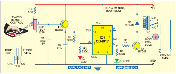
家用电器遥控器
-
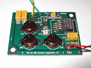
12V 转 28V DC-DC 变换器(基于 LM2585)
-
红外开关
-
DS1669数字电位器
-
HA1377 桥式放大器 BCL 电容 17W(汽车音频)