


【GD32F427开发板试用】EXMC方式驱动LCD屏幕
2024-12-05 来源:elecfans
使用EXMC方式驱动LCD显示屏。
GD32F427VEXMC系统架构图

扩展板硬件
扩展板硬件EXMC接口部分电路图
2.1、开发板接口部分

2.2、LCD接口部分

驱动程序
3.1、exmc.c
#include 'gd32f4xx.h'
#include 'exmc_lcd.h'
/*!
brief lcd peripheral initialize
param[in] none
param[out] none
retval none
*/
void exmc_lcd_init(void)
{
exmc_norsram_parameter_struct lcd_init_struct;
exmc_norsram_timing_parameter_struct lcd_timing_init_struct;
/* EXMC clock enable */
rcu_periph_clock_enable(RCU_EXMC);
/* GPIO clock enable */
rcu_periph_clock_enable(RCU_GPIOD);
rcu_periph_clock_enable(RCU_GPIOE);
/* configure GPIO D[0-15] */
gpio_af_set(GPIOD, GPIO_AF_12, GPIO_PIN_0 | GPIO_PIN_1 | GPIO_PIN_8 | GPIO_PIN_9 |
GPIO_PIN_10 | GPIO_PIN_14 | GPIO_PIN_15);
gpio_mode_set(GPIOD, GPIO_MODE_AF, GPIO_PUPD_PULLUP, GPIO_PIN_0 | GPIO_PIN_1 | GPIO_PIN_8 | GPIO_PIN_9 |
GPIO_PIN_10 | GPIO_PIN_14 | GPIO_PIN_15);
gpio_output_options_set(GPIOD, GPIO_OTYPE_PP, GPIO_OSPEED_50MHZ, GPIO_PIN_0 | GPIO_PIN_1 | GPIO_PIN_8 | GPIO_PIN_9 |
GPIO_PIN_10 | GPIO_PIN_14 | GPIO_PIN_15);
gpio_af_set(GPIOE, GPIO_AF_12, GPIO_PIN_7 | GPIO_PIN_8 | GPIO_PIN_9 | GPIO_PIN_10 |
GPIO_PIN_11 | GPIO_PIN_12 | GPIO_PIN_13 | GPIO_PIN_14 | GPIO_PIN_15);
gpio_mode_set(GPIOE, GPIO_MODE_AF, GPIO_PUPD_PULLUP, GPIO_PIN_7 | GPIO_PIN_8 | GPIO_PIN_9 | GPIO_PIN_10 |
GPIO_PIN_11 | GPIO_PIN_12 | GPIO_PIN_13 | GPIO_PIN_14 | GPIO_PIN_15);
gpio_output_options_set(GPIOE, GPIO_OTYPE_PP, GPIO_OSPEED_50MHZ, GPIO_PIN_7 | GPIO_PIN_8 | GPIO_PIN_9 | GPIO_PIN_10 |
GPIO_PIN_11 | GPIO_PIN_12 | GPIO_PIN_13 | GPIO_PIN_14 | GPIO_PIN_15);
/* configure PE2(EXMC_A23) */
gpio_af_set(GPIOE, GPIO_AF_12, GPIO_PIN_2);
gpio_mode_set(GPIOE, GPIO_MODE_AF, GPIO_PUPD_PULLUP, GPIO_PIN_2);
gpio_output_options_set(GPIOE, GPIO_OTYPE_PP, GPIO_OSPEED_50MHZ, GPIO_PIN_2);
/* configure NOE NWE */
gpio_af_set(GPIOD, GPIO_AF_12, GPIO_PIN_4 | GPIO_PIN_5);
gpio_mode_set(GPIOD, GPIO_MODE_AF, GPIO_PUPD_PULLUP, GPIO_PIN_4 | GPIO_PIN_5);
gpio_output_options_set(GPIOD, GPIO_OTYPE_PP, GPIO_OSPEED_50MHZ, GPIO_PIN_4 | GPIO_PIN_5);
/* configure EXMC NE0 */
gpio_af_set(GPIOD, GPIO_AF_12, GPIO_PIN_7);
gpio_mode_set(GPIOD, GPIO_MODE_AF, GPIO_PUPD_PULLUP, GPIO_PIN_7);
gpio_output_options_set(GPIOD, GPIO_OTYPE_PP, GPIO_OSPEED_50MHZ, GPIO_PIN_7);
lcd_timing_init_struct.asyn_access_mode = EXMC_ACCESS_MODE_A;
lcd_timing_init_struct.syn_data_latency = EXMC_DATALAT_2_CLK;
lcd_timing_init_struct.syn_clk_division = EXMC_SYN_CLOCK_RATIO_2_CLK;
lcd_timing_init_struct.bus_latency = 0;
lcd_timing_init_struct.asyn_data_setuptime = 7;
lcd_timing_init_struct.asyn_address_holdtime = 2;
lcd_timing_init_struct.asyn_address_setuptime = 5;
lcd_init_struct.norsram_region = EXMC_BANK0_NORSRAM_REGION0;
lcd_init_struct.write_mode = EXMC_ASYN_WRITE;
lcd_init_struct.extended_mode = DISABLE;
lcd_init_struct.asyn_wait = DISABLE;
lcd_init_struct.nwait_signal = DISABLE;
lcd_init_struct.memory_write = ENABLE;
lcd_init_struct.nwait_config = EXMC_NWAIT_CONFIG_BEFORE;
lcd_init_struct.wrap_burst_mode = DISABLE;
lcd_init_struct.nwait_polarity = EXMC_NWAIT_POLARITY_LOW;
lcd_init_struct.burst_mode = DISABLE;
lcd_init_struct.databus_width = EXMC_NOR_DATABUS_WIDTH_16B;
lcd_init_struct.memory_type = EXMC_MEMORY_TYPE_SRAM;
lcd_init_struct.address_data_mux = DISABLE;
lcd_init_struct.read_write_timing = &lcd_timing_init_struct;
lcd_init_struct.write_timing = &lcd_timing_init_struct;
exmc_norsram_init(&lcd_init_struct);
exmc_norsram_enable(EXMC_BANK0_NORSRAM_REGION0);
}
3.2、lcd.c
#include 'gd32f4xx.h'
#include 'ili9320.h'
#include 'ili9320_font.h'
#include 'systick.h'
#include < stdio.h >
/*!
brief write data to the selected LCD register
param[in] register_id: the selected register id
param[in] value: the register value to be written
param[out] none
retval none
*/
void lcd_register_write(uint16_t register_id,uint16_t value)
{
*(__IO uint16_t *) (BANK0_LCD_C)= register_id;
*(__IO uint16_t *) (BANK0_LCD_D)= value;
}
/*!
brief read the value of LCD register
param[in] register_id: the register id
param[out] none
retval the register value
*/
uint16_t lcd_register_read(uint8_t register_id)
{
uint16_t data;
*(__IO uint16_t *) (BANK0_LCD_C)= register_id;
data = *(__IO uint16_t *) (BANK0_LCD_D);
return data;
}
/*!
brief write command to LCD register
param[in] value: the register value to be written
param[out] none
retval none
*/
void lcd_command_write(uint16_t value)
{
/* write 16-bit index, then write reg */
*(__IO uint16_t *) (BANK0_LCD_D) = value;
}
/*!
brief prepare to write to the LCD GRAM register(R22h)
param[in] none
param[out] none
retval none
*/
void lcd_gram_write_prepare(void)
{
*(__IO uint16_t *) (BANK0_LCD_C) = 0x0022;
}
/*!
brief write RGB code to the LCD GRAM register
param[in] rgb_code: the pixel color in RGB mode (5-6-5)
param[out] none
retval none
*/
void lcd_gram_write(uint16_t rgb_code)
{
/* write 16-bit GRAM register */
*(__IO uint16_t *) (BANK0_LCD_D) = rgb_code;
}
/*!
brief read data from GRAM
param[in] none
param[out] none
retval GRAM value
*/
uint16_t lcd_gram_read(void)
{
uint16_t data;
/* write GRAM register (R22h) */
*(__IO uint16_t *) (BANK0_LCD_C) = 0x0022;
/* dummy read (invalid data) */
*(__IO uint16_t *) (BANK0_LCD_D);
data = *(__IO uint16_t *) (BANK0_LCD_D);
return data;
}
/*!
brief initialize the LCD
param[in] none
param[out] none
retval none
*/
void lcd_init(void)
{
uint16_t i;
uint16_t device_code;
rcu_periph_clock_enable(RCU_GPIOD);
gpio_mode_set(GPIOD, GPIO_MODE_OUTPUT, GPIO_PUPD_NONE, GPIO_PIN_3|GPIO_PIN_6);
gpio_bit_set(GPIOD, GPIO_PIN_3);
gpio_bit_set(GPIOD, GPIO_PIN_6);
gpio_bit_reset(GPIOD, GPIO_PIN_6);
delay_1ms(200);
gpio_bit_set(GPIOD, GPIO_PIN_6);
delay_1ms(200);
if(1){ /*!< if(device_code == 0x8989) */
lcd_register_write(0x0000,0x0001);
lcd_register_write(0x0003,0xA8A4);
lcd_register_write(0x000C,0x0000);
lcd_register_write(0x000D,0x080C);
lcd_register_write(0x000E,0x2B00);
lcd_register_write(0x001E,0x00B0);
lcd_register_write(0x0001,0x2B3F);
lcd_register_write(0x0002,0x0600);
lcd_register_write(0x0010,0x0000);
lcd_register_write(0x0011,0x6070);
lcd_register_write(0x0005,0x0000);
lcd_register_write(0x0006,0x0000);
lcd_register_write(0x0016,0xEF1C);
lcd_register_write(0x0017,0x0003);
lcd_register_write(0x0007,0x0233);
lcd_register_write(0x000B,0x0000);
lcd_register_write(0x000F,0x0000);
lcd_register_write(0x0041,0x0000);
lcd_register_write(0x0042,0x0000);
lcd_register_write(0x0048,0x0000);
lcd_register_write(0x0049,0x013F);
lcd_register_write(0x004A,0x0000);
lcd_register_write(0x004B,0x0000);
lcd_register_write(0x0044,0xEF00);
lcd_register_write(0x0045,0x0000);
lcd_register_write(0x0046,0x013F);
lcd_register_write(0x0030,0x0707);
lcd_register_write(0x0031,0x0204);
lcd_register_write(0x0032,0x0204);
lcd_register_write(0x0033,0x0502);
lcd_register_write(0x0034,0x0507);
lcd_register_write(0x0035,0x0204);
lcd_register_write(0x0036,0x0204);
lcd_register_write(0x0037,0x0502);
lcd_register_write(0x003A,0x0302);
lcd_register_write(0x003B,0x0302);
lcd_register_write(0x0023,0x0000);
lcd_register_write(0x0024,0x0000);
lcd_register_write(0x0025,0x8000);
lcd_register_write(0x004e,0);
lcd_register_write(0x004f,0);
}else{
return;
}
for(i=50000;i >0;i--);
}
/*!
brief set the cursor of LCD
param[in] x: the row-coordinate
param[in] y: the column-coordinate
param[out] none
retval none
*/
void lcd_cursor_set(uint16_t x,uint16_t y)
{
lcd_register_write(0x004e,x);
lcd_register_write(0x004f,y);
}
/*!
brief clear the LCD screen to the specified color
param[in] color: specified screen color
param[out] none
retval none
*/
void lcd_clear(uint16_t color)
{
uint32_t index=0;
lcd_cursor_set(0,0);
/* prepare to write GRAM */
lcd_gram_write_prepare();
for(index=0;index< 76800;index++){
*(__IO uint16_t *) (BANK0_LCD_D) = color;
}
}
/*!
brief set the point according to the specified position and color
param[in] x: the row-coordinate
param[in] y: the column-coordinate
param[in] point: specified color of the point
param[out] none
retval none
*/
void lcd_point_set(uint16_t x,uint16_t y,uint16_t point)
{
if ((x > 240)||(y > 320)){
return;
}
lcd_cursor_set(x,y);
lcd_gram_write_prepare();
lcd_gram_write(point);
}
/*!
brief get point GRAM according to the specified position
param[in] x: the row-coordinate
param[in] y: the column-coordinate
param[out] none
retval GRAM value of point
*/
uint16_t lcd_point_get(uint16_t x,uint16_t y)
{
uint16_t data;
if ((x > 240)||(y > 320)){
return 0;
}
lcd_cursor_set(x,y);
data = lcd_gram_read();
return data;
}
/*!
brief set window area
param[in] start_x: the start position of row-coordinate
param[in] start_y: the start position of column-coordinate
param[in] end_x: the end position of row-coordinate
param[in] end_y: the end position of column-coordinate
param[out] none
retval none
*/
void lcd_windows_set(uint16_t start_x,uint16_t start_y,uint16_t end_x,uint16_t end_y)
{
lcd_cursor_set(start_x, start_y);
lcd_register_write(0x0050, start_x);
lcd_register_write(0x0052, start_y);
lcd_register_write(0x0051, end_x);
lcd_register_write(0x0053, end_y);
}
/*!
brief draw a horizontal line on LCD screen
param[in] x: the row-coordinate
param[in] start_y: the start column-coordinate
param[in] end_y: the end column-coordinate
param[in] color: specified color of the point
param[in] width: line width
param[out] none
retval none
*/
void lcd_hline_draw(uint16_t x,uint16_t start_y,uint16_t end_y,uint16_t color,uint16_t width)
{
uint16_t i, y;
for (i = 0; i < width; i++) {
uint16_t sx = x + i;
for (y = start_y; y < end_y; y++) {
lcd_point_set(sx, y, color);
}
}
}
/*!
brief draw a rectangle according to the specified position and color
param[in] start_x: the start position of row-coordinate
param[in] start_y: the start position of column-coordinate
param[in] end_x: the end position of row-coordinate
param[in] end_y: the end position of column-coordinate
param[in] point: specified color of the point
param[out] none
retval none
*/
void lcd_rectangle_draw(uint16_t start_x,uint16_t start_y,uint16_t end_x,uint16_t end_y,uint16_t point)
{
uint16_t x,y;
x=start_x;
y=start_y;
/* draw four lines */
for(x=start_x;x< end_x;x++){
/* draw a point */
lcd_point_set(x,y,point);
}
for(y=start_y;y< end_y;y++){
lcd_point_set(x,y,point);
}
for(x=end_x;x >start_x;x--){
lcd_point_set(x,y,point);
}
for(y=end_y;y >start_y;y--){
lcd_point_set(x,y,point);
}
}
/*!
brief fill the specified color to a rectangle
param[in] start_x: the start position of row-coordinate
param[in] start_y: the start position of column-coordinate
param[in] end_x: the end position of row-coordinate
param[in] end_y: the end position of column-coordinate
param[in] color: specified color
param[out] none
retval none
*/
void lcd_rectangle_fill(uint16_t start_x,uint16_t start_y,uint16_t end_x,uint16_t end_y,uint16_t color)
{
uint16_t x, y;
x = start_x;
y = start_y;
for (x = start_x; x < end_x; x++) {
for (y = start_y; y < end_y; y++) {
lcd_point_set(x, y, color);
}
}
}
/*!
brief draw a picture on LCD screen according to the specified position
param[in] start_x: the start position of row-coordinate
param[in] start_y: the start position of column-coordinate
param[in] end_x: the end position of row-coordinate
param[in] end_y: the end position of column-coordinate
param[in] pic: the picture pointer
param[out] none
retval none
*/
void lcd_picture_draw(uint16_t start_x,uint16_t start_y,uint16_t end_x,uint16_t end_y,uint16_t *pic)
{
uint32_t i, total;
uint16_t *picturepointer = pic;
uint16_t x,y;
x = start_x;
y = start_y;
total = (end_x - start_x + 1) * (end_y - start_y + 1);
for(i = 0; i < total; i ++){
/* set point according to the specified position and color */
lcd_point_set(x,y,*picturepointer++);
x++;
if(x > end_x){
y++;
x = start_x;
}
}
}
/*!
brief display a char on LCD screen according to the specified position
param[in] x: the start position of row-coordinate
param[in] y: the start position of column-coordinate
param[in] c: the char
param[in] char_color: the color of char
param[in] c_format: the struct of char format
font: CHAR_FONT_8_16 or CHAR_FONT_16_24
direction: CHAR_DIRECTION_HORIZONTAL or CHAR_DIRECTION_VERTICAL
char_color: the color of char
bk_color: the color of backgroud
param[out] none
retval none
*/
void lcd_char_display(uint16_t x,uint16_t y,uint8_t c,char_format_struct c_format)
{
uint16_t i = 0, j = 0;
uint8_t temp_char = 0;
uint16_t temp_char_16 = 0;
if(CHAR_FONT_8_16 == c_format.font){ /* 8x16 ASCII */
for (i = 0; i < 16; i++) {
temp_char = ascii_8x16[((c - 0x20) * 16) + i];
if(CHAR_DIRECTION_HORIZONTAL == c_format.direction){
for (j = 0; j < 8; j++) {
if (((temp_char > > (7 - j)) & 0x01) == 0x01) {
/* set point of char */
lcd_point_set(x - i, y + j, c_format.char_color);
} else {
/* set point of background */
lcd_point_set(x - i, y + j, c_format.bk_color);
}
}
}else{
for (j = 0; j < 8; j++) {
if (((temp_char > > (7 - j)) & 0x01) == 0x01) {
/* set point of char */
lcd_point_set(x + j, y + i, c_format.char_color);
} else {
/* set point of background */
lcd_point_set(x + j, y + i, c_format.bk_color);
}
}
}
}
}else if(CHAR_FONT_16_24 == c_format.font){ /* 16x24 ASCII */
for (i = 0; i < 24; i++) {
temp_char_16 = ASCII_Table_16x24[((c - 0x20) * 24) + i];
if(CHAR_DIRECTION_HORIZONTAL == c_format.direction){
for (j = 0; j < 16; j++) {
if (((temp_char_16 > > j) & 0x01) == 0x01) {
/* set point of char */
lcd_point_set(x - i, y + j, c_format.char_color);
} else {
/* set point of background */
lcd_point_set(x - i, y + j, c_format.bk_color);
}
}
}else{
for (j = 0; j < 16; j++) {
if (((temp_char_16 > > j) & 0x01) == 0x01) {
/* set point of char */
lcd_point_set(x + j, y + i, c_format.char_color);
} else {
/* set point of background */
lcd_point_set(x + j, y + i, c_format.bk_color);
}
}
}
}
}
}
3.3、main.c
#include 'gd32f4xx.h'
//#include 'gd32f427v_start.h'
#include 'systick.h'
#include < stdio.h >
#include 'usart.h'
#include 'exmc_lcd.h'
#include 'ili9320.h'
#include 'picture.h'
char_format_struct char_format;
uint8_t gd_website_string[]={'www.gigadevice.com'} ;
int main(void)
{
uint16_t i;
/* configure systick */
systick_config();
init_usart();
exmc_lcd_init();
lcd_init();
lcd_clear(WHITE);
lcd_picture_draw(40,100,40+160-1,100+87-1,(uint16_t *)(picture + BMP_HEADSIZE));
lcd_rectangle_draw(10,10,230,310,BLUE);
/* configure char format */
char_format.char_color = BLUE;
char_format.bk_color = WHITE;
char_format.direction = CHAR_DIRECTION_VERTICAL;
char_format.font = CHAR_FONT_8_16;
/* draw character on LCD screen */
for (i = 0; i < sizeof(gd_website_string)-1; i++){
lcd_char_display((50+8*i), 180+20, *(gd_website_string+i),char_format);
}
/* enable the LEDs GPIO clock */
rcu_periph_clock_enable(RCU_GPIOA);
rcu_periph_clock_enable(RCU_GPIOC);
/* configure LED2 GPIO port */
gpio_mode_set(GPIOC, GPIO_MODE_OUTPUT, GPIO_PUPD_NONE, GPIO_PIN_6);
gpio_output_options_set(GPIOC, GPIO_OTYPE_PP, GPIO_OSPEED_50MHZ, GPIO_PIN_6);
/* reset LED2 GPIO pin */
gpio_bit_reset(GPIOC, GPIO_PIN_6);
//PA9/PA10
gpio_mode_set(GPIOA, GPIO_MODE_OUTPUT, GPIO_PUPD_NONE, GPIO_PIN_9);
gpio_mode_set(GPIOA, GPIO_MODE_OUTPUT, GPIO_PUPD_NONE, GPIO_PIN_10);
gpio_output_options_set(GPIOA, GPIO_OTYPE_PP, GPIO_OSPEED_50MHZ, GPIO_PIN_9);
gpio_output_options_set(GPIOA, GPIO_OTYPE_PP, GPIO_OSPEED_50MHZ, GPIO_PIN_10);
while(1) {
/* turn on LED2 */
gpio_bit_set(GPIOC, GPIO_PIN_6);
gpio_bit_set(GPIOA, GPIO_PIN_9);
gpio_bit_reset(GPIOA, GPIO_PIN_10);
//lcd_register_write(0x0000,0x5555);
delay_1ms(200);
/* turn off LED2 */
gpio_bit_reset(GPIOA, GPIO_PIN_9);
gpio_bit_set(GPIOA, GPIO_PIN_10);
gpio_bit_reset(GPIOC, GPIO_PIN_6);
//lcd_register_write(0x0000,0xFFFF);
delay_1ms(200);
printf('a usart transmit test example!rn');
}
}
屏幕显示
屏幕上显示GD的logo

- 六大全新产品系列推出,MCX A微控制器家族迎来创新
- 意法半导体全新STM32C5系列,重新定义入门级微控制器性能与价值,赋能万千智能设备
- 从控制到系统:TI利用边缘AI重塑嵌入式MCU的边界
- 模组复用与整机重测在SRRC、CCC、CTA/NAL认证中的实践操作指南
- 有源晶振与无源晶振的六大区别详解
- 英飞凌持续巩固全球微控制器市场领导地位
- 使用 Keil Studio for Visual Studio Code开发 STM32 设备
- 蓝牙信道探测技术原理与开发套件实践
- LoRa、LoRaWAN、NB-IoT与4G DTU技术对比及工业无线方案选型分析
- Microchip 推出生产就绪型全栈边缘 AI 解决方案,赋能MCU和MPU实现 智能实时决策
-

【TI MSPM0 应用实战】智能小车+工业角度编码器+血氧仪+烟雾探测器!硬核参考设计详解!
-

2022 Digi-Key KOL 系列: 你见过1GHz主频的单片机吗?Teensy 4.1开发板介绍
-

TI 新一代 C2000™ 微控制器:全方位助力伺服及马达驱动应用
-

MSP430电容触摸技术 - 防水Demo演示
-

直播回放: Microchip Timberwolf™ 音频处理器在线研讨会
-

基于灵动MM32W0系列MCU的指夹血氧仪控制及OTA升级应用方案分享
-
1瓦四级调频发射机
-
500W MOS场效应管电源逆变器,12V转110V/220V
-
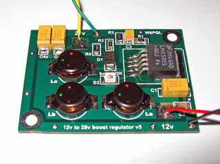
12V 转 28V DC-DC 变换器(基于 LM2585)
-
红外开关
-
12V转110V/220V 500W逆变器
-
DS1669数字电位器