


STM32系统时钟
2025-09-17 来源:cnblogs
一、时钟树

STM32有4个时钟源:
1)HSE(高速外部时钟源) 外部晶振作为时钟源,范围为4~16MHz,常取为8MHz
2)HSI(高速内部时钟源) 由内部RC振荡器产生,频率为8MHz,但不稳定
3)LSE(低速外部时钟) 以外部晶振作为时钟源,主要供给实时时钟模块,一般用32.768KHz。
4)LSI(低速内部时钟) 由内部RC振荡器产生,也是提供给实时时钟模块,频率约为40KHz。
二、系统启动过程中时钟设置过程
以使用STM32库函数SystemInit为例进行说明:
上电后:默认使用HSI
SystemInit: 倘若调用了函数SetSysClockTo72,将启用外部晶振HSE,并将系统时钟设置到72MHz。
附SetSysClockTo72函数代码:
/**
* @brief Sets System clock frequency to 72MHz and configure HCLK, PCLK2
* and PCLK1 prescalers.
* @note This function should be used only after reset.
* @param None
* @retval None
*/
static void SetSysClockTo72(void)
{
__IO uint32_t StartUpCounter = 0, HSEStatus = 0;
/* SYSCLK, HCLK, PCLK2 and PCLK1 configuration ---------------------------*/
/* Enable HSE */
RCC->CR |= ((uint32_t)RCC_CR_HSEON);
/* Wait till HSE is ready and if Time out is reached exit */
do
{
HSEStatus = RCC->CR & RCC_CR_HSERDY;
StartUpCounter++;
} while((HSEStatus == 0) && (StartUpCounter != HSE_STARTUP_TIMEOUT));
if ((RCC->CR & RCC_CR_HSERDY) != RESET)
{
HSEStatus = (uint32_t)0x01;
}
else
{
HSEStatus = (uint32_t)0x00;
}
if (HSEStatus == (uint32_t)0x01)
{
/* Enable Prefetch Buffer */
FLASH->ACR |= FLASH_ACR_PRFTBE;
/* Flash 2 wait state */
FLASH->ACR &= (uint32_t)((uint32_t)~FLASH_ACR_LATENCY);
FLASH->ACR |= (uint32_t)FLASH_ACR_LATENCY_2;
/* HCLK = SYSCLK */
RCC->CFGR |= (uint32_t)RCC_CFGR_HPRE_DIV1;
/* PCLK2 = HCLK */
RCC->CFGR |= (uint32_t)RCC_CFGR_PPRE2_DIV1;
/* PCLK1 = HCLK */
RCC->CFGR |= (uint32_t)RCC_CFGR_PPRE1_DIV2;
#ifdef STM32F10X_CL
/* Configure PLLs ------------------------------------------------------*/
/* PLL2 configuration: PLL2CLK = (HSE / 5) * 8 = 40 MHz */
/* PREDIV1 configuration: PREDIV1CLK = PLL2 / 5 = 8 MHz */
RCC->CFGR2 &= (uint32_t)~(RCC_CFGR2_PREDIV2 | RCC_CFGR2_PLL2MUL |
RCC_CFGR2_PREDIV1 | RCC_CFGR2_PREDIV1SRC);
RCC->CFGR2 |= (uint32_t)(RCC_CFGR2_PREDIV2_DIV5 | RCC_CFGR2_PLL2MUL8 |
RCC_CFGR2_PREDIV1SRC_PLL2 | RCC_CFGR2_PREDIV1_DIV5);
/* Enable PLL2 */
RCC->CR |= RCC_CR_PLL2ON;
/* Wait till PLL2 is ready */
while((RCC->CR & RCC_CR_PLL2RDY) == 0)
{
}
/* PLL configuration: PLLCLK = PREDIV1 * 9 = 72 MHz */
RCC->CFGR &= (uint32_t)~(RCC_CFGR_PLLXTPRE | RCC_CFGR_PLLSRC | RCC_CFGR_PLLMULL);
RCC->CFGR |= (uint32_t)(RCC_CFGR_PLLXTPRE_PREDIV1 | RCC_CFGR_PLLSRC_PREDIV1 |
RCC_CFGR_PLLMULL9);
#else
/* PLL configuration: PLLCLK = HSE * 9 = 72 MHz */
RCC->CFGR &= (uint32_t)((uint32_t)~(RCC_CFGR_PLLSRC | RCC_CFGR_PLLXTPRE |
RCC_CFGR_PLLMULL));
RCC->CFGR |= (uint32_t)(RCC_CFGR_PLLSRC_HSE | RCC_CFGR_PLLMULL9);
#endif /* STM32F10X_CL */
/* Enable PLL */
RCC->CR |= RCC_CR_PLLON;
/* Wait till PLL is ready */
while((RCC->CR & RCC_CR_PLLRDY) == 0)
{
}
/* Select PLL as system clock source */
RCC->CFGR &= (uint32_t)((uint32_t)~(RCC_CFGR_SW));
RCC->CFGR |= (uint32_t)RCC_CFGR_SW_PLL;
/* Wait till PLL is used as system clock source */
while ((RCC->CFGR & (uint32_t)RCC_CFGR_SWS) != (uint32_t)0x08)
{
}
}
else
{ /* If HSE fails to start-up, the application will have wrong clock
configuration. User can add here some code to deal with this error */
}
}
- 意法半导体中国本地造STM32微控制器启动规模量产
- 意法半导体全新STM32C5系列,重新定义入门级微控制器性能与价值,赋能万千智能设备
- 使用 Keil Studio for Visual Studio Code开发 STM32 设备
- 基于机智云与STM32的智能拐杖安全监测系统在养老物联网中的应用
- 内置全栈安全,一站式满足CRA法案与IEC 62443标准——米尔STM32MP257核心板
- 如何用 STM32 FLASH 实现等效 100 万次擦写的 EEPROM 功能?
- 实战解析:通过一个小项目掌握STM32所有外设
- STM32学了两年半,却还是不会做项目
- 意法半导体推出最新STM32MP21微处理器,兼具高性价比、低功耗、高灵活性
- 基于STM32的矿井作业环境监测系统设计与实现
- 六大全新产品系列推出,MCX A微控制器家族迎来创新
- 意法半导体全新STM32C5系列,重新定义入门级微控制器性能与价值,赋能万千智能设备
- 模组复用与整机重测在SRRC、CCC、CTA/NAL认证中的实践操作指南
- 有源晶振与无源晶振的六大区别详解
- 英飞凌持续巩固全球微控制器市场领导地位
- 使用 Keil Studio for Visual Studio Code开发 STM32 设备
- 从控制到系统:TI利用边缘AI重塑嵌入式MCU的边界
- 蓝牙信道探测技术原理与开发套件实践
- Microchip 推出生产就绪型全栈边缘 AI 解决方案,赋能MCU和MPU实现 智能实时决策
- LoRa、LoRaWAN、NB-IoT与4G DTU技术对比及工业无线方案选型分析
-

【TI MSPM0 应用实战】智能小车+工业角度编码器+血氧仪+烟雾探测器!硬核参考设计详解!
-

2022 Digi-Key KOL 系列: 你见过1GHz主频的单片机吗?Teensy 4.1开发板介绍
-

TI 新一代 C2000™ 微控制器:全方位助力伺服及马达驱动应用
-

MSP430电容触摸技术 - 防水Demo演示
-

直播回放: Microchip Timberwolf™ 音频处理器在线研讨会
-

基于灵动MM32W0系列MCU的指夹血氧仪控制及OTA升级应用方案分享
-
1瓦线性调频增强器
-
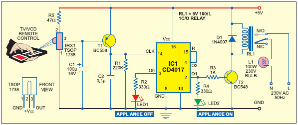
家用电器遥控器
-
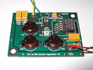
12V 转 28V DC-DC 变换器(基于 LM2585)
-
红外开关
-
DS1669数字电位器
-
HA1377 桥式放大器 BCL 电容 17W(汽车音频)