


STM32串口中断实例二
2025-09-16 来源:cnblogs
int main(void)
{
uint8_t a=0;//LED高低电压控制
/* System Clocks Configuration */
RCC_Configuration(); //系统时钟设置
/*嵌套向量中断控制器
说明了USART1抢占优先级级别0(最多1位) ,和子优先级级别0(最多7位) */
NVIC_Configuration(); //中断源配置
/*对控制LED指示灯的IO口进行了初始化,将端口配置为推挽上拉输出,口线速度为50Mhz。PA9,PA10端口复用为串口1的TX,RX。
在配置某个口线时,首先应对它所在的端口的时钟进行使能。否则无法配置成功,由于用到了端口B, 因此要对这个端口的时钟
进行使能,同时由于用到复用IO口功能用于配置串口。因此还要使能AFIO(复用功能IO)时钟。*/
GPIO_Configuration(); //端口初始化
USART_Config(USART1); //串口1初始化
while (1)
{
if(rec_f == 1)
{
//判断是否收到一帧有效数据
rec_f = 0;
for(i=0; i USART_SendChar(USART1,TxBuffer1[i]); Delay(0x0000ff0); } /*for(i=0;i USART_SendChar(USART1,RxBuffer1[i]); } */ if(a==0) { GPIO_SetBits(GPIOD, GPIO_Pin_2); //LED1 明暗闪烁 a=1; } else { GPIO_ResetBits(GPIOD, GPIO_Pin_2); a=0; } } } } main函数如上。 相关变量 uint8_t TxBuffer1[] = 'USART Interrupt Example: This is USART1 DEMO'; uint8_t RxBuffer1[], rec_f, tx_flag, i; __IO uint8_t TxCounter1 = 0x00; __IO uint8_t RxCounter1 = 0x00; uint32_t Rec_Len; 串口中断函数配置如下所示: //-------------------------------------------------------------------------------------- void USART_SendChar(USART_TypeDef* USARTx,uint8_t data) { USART_SendData(USARTx,data); while(USART_GetFlagStatus(USARTx,USART_FLAG_TC)==RESET); } //-------------------------------------------------------------------------------------- void USART_Config(USART_TypeDef* USARTx) { USART_InitStructure.USART_BaudRate = 19200; //速率19200bps USART_InitStructure.USART_WordLength = USART_WordLength_8b; //数据位8位 USART_InitStructure.USART_StopBits = USART_StopBits_1; //停止位1位 USART_InitStructure.USART_Parity = USART_Parity_No; //无校验位 USART_InitStructure.USART_HardwareFlowControl = USART_HardwareFlowControl_None; //无硬件流控 USART_InitStructure.USART_Mode = USART_Mode_Rx | USART_Mode_Tx; //收发模式 /* Configure USARTx */ USART_Init(USARTx, &USART_InitStructure); //配置串口参数函数 /* Enable USARTx Receive and Transmit interrupts */ USART_ITConfig(USARTx, USART_IT_RXNE, ENABLE); //使能接收中断 USART_ITConfig(USARTx, USART_IT_TXE, ENABLE); //使能发送缓冲空中断 /* Enable the USARTx */ USART_Cmd(USARTx, ENABLE); } //-------------------------------------------------------------------------------------- void Delay(__IO uint32_t nCount) { for(; nCount!=0; nCount--); } /*-------------------------------------------------------------------------------------- 系统时钟配置为72MHZ+外设时钟配置*/ void RCC_Configuration(void) { SystemInit(); RCC_APB2PeriphClockCmd( RCC_APB2Periph_USART1 | RCC_APB2Periph_GPIOD |RCC_APB2Periph_GPIOA, ENABLE); } //-------------------------------------------------------------------------------------- void GPIO_Configuration(void) { GPIO_InitStructure.GPIO_Pin = GPIO_Pin_2; //LED1控制--PD2 GPIO_InitStructure.GPIO_Mode = GPIO_Mode_Out_PP; //推挽输出 GPIO_InitStructure.GPIO_Speed = GPIO_Speed_50MHz; GPIO_Init(GPIOD, &GPIO_InitStructure); GPIO_InitStructure.GPIO_Pin = GPIO_Pin_9; //USART1 TX GPIO_InitStructure.GPIO_Mode = GPIO_Mode_AF_PP; //复用推挽输出 GPIO_Init(GPIOA, &GPIO_InitStructure); //A端口 GPIO_InitStructure.GPIO_Pin = GPIO_Pin_10; //USART1 RX GPIO_InitStructure.GPIO_Mode = GPIO_Mode_IN_FLOATING; //复用开漏输入 GPIO_Init(GPIOA, &GPIO_InitStructure); //A端口 } //-------------------------------------------------------------------------------------- void NVIC_Configuration(void) { /* 结构声明*/ NVIC_InitTypeDef NVIC_InitStructure; /* Configure the NVIC Preemption Priority Bits */ /* Configure one bit for preemption priority */ /* 优先级组 说明了抢占优先级所用的位数,和子优先级所用的位数 在这里是1, 7 */ NVIC_PriorityGroupConfig(NVIC_PriorityGroup_0); NVIC_InitStructure.NVIC_IRQChannel = USART1_IRQn; //设置串口1中断 NVIC_InitStructure.NVIC_IRQChannelPreemptionPriority = 0; //抢占优先级 0 NVIC_InitStructure.NVIC_IRQChannelSubPriority = 0; //子优先级为0 NVIC_InitStructure.NVIC_IRQChannelCmd = ENABLE; //使能 NVIC_Init(&NVIC_InitStructure); } 在中断服务函数中编写usart函数。 //串口1 中断服务程序 void USART1_IRQHandler(void) { unsigned int i; //判断读寄存器是否非空 if(USART_GetITStatus(USART1, USART_IT_RXNE) != RESET) { //将读寄存器的数据缓存到接收缓冲区里 RxBuffer1[RxCounter1++] = USART_ReceiveData(USART1); //判断结束标志是否是0x0d 0x0a if(RxBuffer1[RxCounter1-2] == 0x0d && RxBuffer1[RxCounter1-1] == 0x0a) { for(i=0; i< RxCounter1; i++) TxBuffer1[i] = RxBuffer1[i]; //将接收缓冲器的数据转到发送缓冲区,准备转发 //接收成功标志 rec_f = 1; //发送缓冲区结束符 TxBuffer1[RxCounter1] = 0; TxCounter1 = RxCounter1; RxCounter1 = 0; } } //这段是为了避免STM32 USART 第一个字节发不出去的BUG if(USART_GetITStatus(USART1, USART_IT_TXE) != RESET) { //禁止发缓冲器空中断, USART_ITConfig(USART1, USART_IT_TXE, DISABLE); } } 运行结果如下,在发送去不填写任何字符,直接发送,显示RT Interrupt Example: This is USART1 DEMO,说明前三个字符已经被占用替换了。 试验平台alienteck mini stm32V1.9 stm32f103rbt6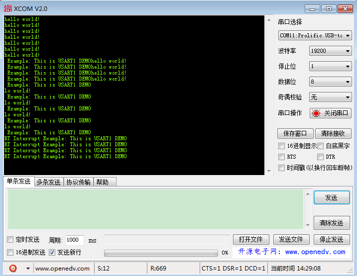
下一篇:stm32串口——标志位学习
- 意法半导体中国本地造STM32微控制器启动规模量产
- 意法半导体全新STM32C5系列,重新定义入门级微控制器性能与价值,赋能万千智能设备
- 使用 Keil Studio for Visual Studio Code开发 STM32 设备
- 基于机智云与STM32的智能拐杖安全监测系统在养老物联网中的应用
- 内置全栈安全,一站式满足CRA法案与IEC 62443标准——米尔STM32MP257核心板
- 如何用 STM32 FLASH 实现等效 100 万次擦写的 EEPROM 功能?
- 实战解析:通过一个小项目掌握STM32所有外设
- STM32学了两年半,却还是不会做项目
- 意法半导体推出最新STM32MP21微处理器,兼具高性价比、低功耗、高灵活性
- 基于STM32的矿井作业环境监测系统设计与实现
- 六大全新产品系列推出,MCX A微控制器家族迎来创新
- 意法半导体全新STM32C5系列,重新定义入门级微控制器性能与价值,赋能万千智能设备
- 模组复用与整机重测在SRRC、CCC、CTA/NAL认证中的实践操作指南
- 有源晶振与无源晶振的六大区别详解
- 英飞凌持续巩固全球微控制器市场领导地位
- 使用 Keil Studio for Visual Studio Code开发 STM32 设备
- 从控制到系统:TI利用边缘AI重塑嵌入式MCU的边界
- 蓝牙信道探测技术原理与开发套件实践
- Microchip 推出生产就绪型全栈边缘 AI 解决方案,赋能MCU和MPU实现 智能实时决策
- LoRa、LoRaWAN、NB-IoT与4G DTU技术对比及工业无线方案选型分析
-

【TI MSPM0 应用实战】智能小车+工业角度编码器+血氧仪+烟雾探测器!硬核参考设计详解!
-

2022 Digi-Key KOL 系列: 你见过1GHz主频的单片机吗?Teensy 4.1开发板介绍
-

TI 新一代 C2000™ 微控制器:全方位助力伺服及马达驱动应用
-

MSP430电容触摸技术 - 防水Demo演示
-

直播回放: Microchip Timberwolf™ 音频处理器在线研讨会
-

基于灵动MM32W0系列MCU的指夹血氧仪控制及OTA升级应用方案分享
-
1瓦线性调频增强器
-
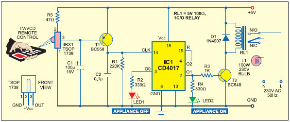
家用电器遥控器
-
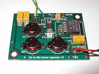
12V 转 28V DC-DC 变换器(基于 LM2585)
-
红外开关
-
DS1669数字电位器
-
HA1377 桥式放大器 BCL 电容 17W(汽车音频)