


一款基于WIFI传输的便携式体征信息监测系统设计
2025-08-25 来源:eepw
As time goes by, people are increasingly concerned about their own and their families' health. However, existing monitoring devices for individual vital signs have struggled to gain market share due to their cumbersome operation, high level of technical expertise, limited information display, and limited specificity. This article introduces a simple and convenient intelligent vital sign monitoring system with low power consumption, ease of use, and simple operation.
This monitoring system integrates real-time monitoring of multiple vital signs, including temperature and pulse, and, combined with the rapidly expanding Android smartphone ecosystem, minimizes user interaction. With simple setup, the intelligent software allows users to intuitively access multiple vital signs in real time or at intervals, and can even trigger alarms for signs exceeding set limits. Furthermore, the intelligent terminal software optimizes and organizes data, creating a personal database of vital signs, analyzing individual situations and providing comprehensive health recommendations.
1 Overall structure and working principle
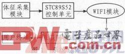
The system adopts a modular design principle based on the principles of safety, reliability, ease of use, and economy. The data acquisition component, based on the STC89S52 microcontroller, utilizes modules such as the DS18B20 temperature sensor and the HK2000B piezoelectric pulse sensor to collect physiological sign information. After filtering, amplification, and digitization, the data is wirelessly transmitted to the server via the HLKWIFIM03 module and then pushed to the user terminal for display. The overall system block diagram is shown in Figure 1.
2 System Design
2.1 Hardware Circuit Design
2.1.1 Pulse Detection Module Design
The cyclical contraction and relaxation of the ventricles causes the contraction and relaxation of the aorta, causing blood pressure to propagate in waves from the aortic root throughout the arterial system. This wave is called a pulse wave. The pulse wave's comprehensive information, including its shape, intensity, rate, and rhythm, largely reflects many physiological and pathological blood flow characteristics within the cardiovascular system.
Considering the product's price and required accuracy, this module selected the HK-2000B integrated pulse sensor based on polyvinylidene fluoride piezoelectric film, developed by the Hefei Huake Electronic Technology Research Institute. This sensor utilizes a highly integrated process, integrating a force-sensitive element (PVDF piezoelectric film), a sensitivity and temperature compensation element, a temperature sensor, and signal conditioning circuitry. It uses a piezoelectric principle to acquire signals and output analog signals, producing a complete pulse wave voltage signal. This product is primarily used for noninvasive cardiovascular function testing, pregnancy-induced hypertension testing, and Traditional Chinese Medicine pulse diagnosis. The main components of the pulse acquisition section are shown in Figure 2.
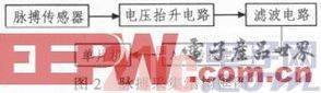
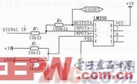
The analog signal voltage range of the pulse sensor output is -0.1 to 0.6 V. To eliminate the negative sign and meet the needs of the subsequent single-ended input A/D converter, a voltage boost circuit is designed as shown in Figure 3.
The pulse signal output by the sensor has a very low frequency and is easily susceptible to interference, including interference from the 50 Hz power supply frequency and artifacts caused by body tremors and mental stress. Since the human pulse frequency ranges from 0.1 to 70 Hz, a low-pass filter with a cutoff frequency of 100 Hz is used to filter out system interference, including voltage rise and power supply interference. The signal is then transmitted to the A/D converter for the next step of analog-to-digital conversion.
The MAX187 is a 12-bit successive approximation serial A/D converter chip with fast conversion speed and low power consumption. It connects to a microcontroller using a 3-wire serial data interface. The interface circuit between the MAX187 and the STC89S52 microcontroller is shown in Figure 4.
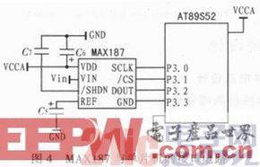
The STC89S52's P3.0, P3.1, and P3.2 pins are connected to the MAX187's SCLK, CS, and DOUT pins, respectively. By controlling the MAX187's serial port timing, continuous A/D conversion read and write operations are performed. The power supply requires decoupling, typically using a 4.7μF capacitor in parallel with a 0.1μF capacitor. When using the internal 4.096 V reference voltage, connect a 4.7μF decoupling capacitor to pin 4. The analog input voltage range is 0 to 4.096 V. If the analog input voltage is outside this range, external circuitry is required to convert the voltage range.
2.1.2 Body temperature detection module design
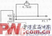
The body temperature module uses the DS18B20, a single-wire digital temperature sensor manufactured by DALLAS. Its compact size allows for easy on-body monitoring, and its digital output makes it easy to use. The temperature measurement range is -55°C to +125°C. The resolution can be set to 9 to 12 bits. When the resolution is set to 12 bits, the conversion accuracy is ±0.0625°C. The connection circuit to the microcontroller is shown in Figure 5.
The DS18B20's internal memory is divided into two parts. One part is a high-speed scratchpad RAM containing 8 consecutive bytes. Temperature information is stored in the first two bytes, with the lower eight bits of the temperature stored in the first byte and the upper eight bits in the second byte. Volatile copies of TH and TL are stored in bytes 3 and 4, respectively, and a volatile copy of the configuration register is stored in byte 5. The contents of these three bytes are refreshed at every power-on reset. Bytes 6, 7, and 8 are used for internal calculations. The ninth byte is a redundancy check byte. The other part is a non-volatile, electrically erasable E2ROM that stores the high and low temperature triggers TH and TL, as well as the configuration register. The DS18B20 can programmatically set the maximum and minimum alarm temperatures TH and TL, implementing temperature-limited alarm control.
Before each read or write operation on the DS18B20, it must be reset (i.e. initialized). After the reset is successful, a ROM instruction is sent, and finally a RAM instruction is sent.
2.1.3 WIFI wireless transmission module
For the wireless transmission module, we used the brand-new third-generation embedded UART-Wifi module HLK-WIFI-M03 (Figure 6), launched by Hailingke (Hong Kong) Co., Ltd. This UART-Wifi module is a UART-based, Wi-Fi-compliant embedded module with a built-in IEEE 802.11 and TCP/IP stacks, enabling the conversion of user serial port data to the wireless network.
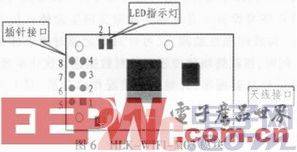
Pin 5: VDD connected to 3.3V power supply; Pin 8: GND connected to ground; Pin 6: RXD connected to microcontroller TXD; Pin 7: TXD connected to microcontroller RXD
First, set the WiFi module to transparent transmission mode, join the local area network (LAN) where the AP resides, and establish a socket connection with the server within the network. This socket acts as a "virtual wire" between the two communicating parties. Collected vital signs information is transparently transmitted directly to the server via this "virtual wire." Software installed on the server integrates and analyzes the data. If a threshold is exceeded, the server immediately sends an alarm signal and the user's vital signs information via the internet to the user's family members' mobile phones or other mobile devices. The alarm can also be sent to a hospital for emergency treatment.
2.2 Software Design
We chose the Android smartphone as the application platform for user terminals. Android is a mobile software development platform supported by Google and the Open Handset Alliance. It supports a variety of wireless network connection methods, such as GPRS, WiFi, and Bluetooth. Through these methods, Android phones can easily communicate over wireless networks, accessing the Internet and various network servers. The Android framework also provides support for communication protocols such as HTTP.
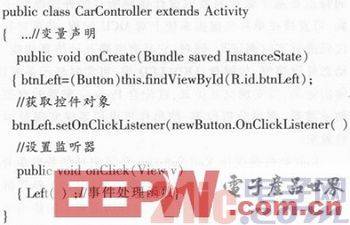
Android applications are developed based on many Android API components. The following are some of the main API components: The current active program is the most commonly used application component. An activity can be simply understood as a screen that the user sees, called an "activity." It is mainly used to handle the overall work of the program, and implements running, pausing, and stopping states by calling methods such as onCreate(), onStart(), onRestart(), onResume(), onStop(), and onDestroy(). For example, it listens for events such as keystrokes and touch screens, specifies an image display View, and starts other activities. Android uses the Intent class to start other activities. It calls the startActivity(myIntent) method to trigger the parsing of the myIntent action. After receiving the myIntent notification, the new activity begins running. For example, switching activities can achieve switching display layouts. The ContentProvider class is a special type of data storage that implements data storage and sharing. A Service is an application component that runs in the background and does not directly interact with the user. The current active program can use Context.
StartService() starts a background service and can also communicate with the background service through Context.bindService(). In Android Java programs, controls that implement human-computer interaction are handled through events, and it is necessary to specify the event listeners used by the controls. The event response code is as follows:
3 System Debugging
First, configure the parameters of the WIFI module so that it works in transparent transmission mode and can transmit data at any time. The data is displayed on the mobile phone interface through wireless transmission through the microcontroller's write operation command to the serial port.
The pulse is then calibrated and the human pulse data measured by the system is compared with that measured by a standard pulse meter. The results show that the error between the two is within ±5 Hz.
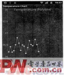
Finally, a temperature test was conducted. After debugging the software and hardware, a temperature reading was displayed on the interface. This reading was then compared with the data measured by a standard thermometer, indicating a ±0.1°C difference. The upper and lower temperature thresholds were set at 38°C and 35°C, respectively. If the given test temperature was below 35°C or above 38°C, an alarm would automatically pop up on the user's phone.
The body temperature collection display is shown in Figure 6, where the horizontal axis is the software running time and the vertical axis is the body temperature value.
The heart rate collection display is shown in Figure 7, which is recorded according to time and uploaded to the server.

4 Conclusion
This monitoring system integrates real-time monitoring of multiple vital signs, including body temperature and heart rate, and integrates with the rapidly growing popularity of mobile smart systems. This data is transmitted via WiFi to a signal processing center, which compiles and processes it to generate waveforms and data results. These are then transmitted via the network to the receiving end, where they are integrated with the user's Android device for data display and feedback. This user-friendly interactive interface manages vital sign information, enabling remote monitoring, analysis, and alerting. It boasts low power consumption, ease of use, and simple operation, promising broad application prospects.
下一篇:单片机实验:外部中断按键
-

【TI MSPM0 应用实战】智能小车+工业角度编码器+血氧仪+烟雾探测器!硬核参考设计详解!
-

2022 Digi-Key KOL 系列: 你见过1GHz主频的单片机吗?Teensy 4.1开发板介绍
-

TI 新一代 C2000™ 微控制器:全方位助力伺服及马达驱动应用
-

MSP430电容触摸技术 - 防水Demo演示
-

直播回放: Microchip Timberwolf™ 音频处理器在线研讨会
-

基于灵动MM32W0系列MCU的指夹血氧仪控制及OTA升级应用方案分享
-

PCM2707 USB音频数模转换芯片声卡
-

TDA2050立体声音频功率放大器
-

基于LM317和TIP42的40V 2A电源
-

序列式刹车/转向灯
-

使用 PMIC 延长便携式应用中的电池寿命
-

智能工厂的智能电源设计